Linux驱动 | 手写一个设备树使用的实例,
Linux驱动 | 手写一个设备树使用的实例,

一、前言
设备树是每一个Linux驱动工程师都必须掌握的一个知识点,有很多之前做单片机的朋友刚接触Linux驱动时,会一脸懵!
其实设备树的使用并没有大家想像的那么复杂,对于大部分工程师来说,只要会修改即可。
很多粉丝留言说,希望彭老师提供一个设备树到驱动解析的实例。
必须安排!
在学习设备树之前,大家一定要搞清楚什么是platform总线,请详细学习下面这篇文章:
《手把手教Linux驱动10-platform总线详解》
关于设备树理论部分内容请学习下面这篇文章:
《手把手教linux驱动11-linux设备驱动统一模型》
关于驱动基础文章,可以去B站学习一口君的入门视频:
《从学Linux驱动入门视频》
https://www.bilibili.com/video/BV1d5411A7VJ?spm_id_from=333.999.0.0
有了这些基础知识后,我们就可以来编写一个设备树的实例,
下面彭老师就给大家讲解如何自己添加一个设备树节点,并如何在驱动中提取出设备树的信息。
老规矩,代码从0开始编写,并且全部验证通过,并分享给大家。
二、测试平台
本次测试在开发板上操作,操作环境如下:
1. 编译环境
- ubuntu 16.04
2. 交叉编译工具
- root@ubuntu:/home/peng/linux-3.14# arm-none-linux-gnueabi-gcc -v
- Using built-in specs.
- COLLECT_GCC=arm-none-linux-gnueabi-gcc
- COLLECT_LTO_WRAPPER=/home/peng/toolchain/gcc-4.6.4/bin/../libexec/gcc/arm-arm1176jzfssf-linux-gnueabi/4.6.4/lto-wrapper
- Target: arm-arm1176jzfssf-linux-gnueabi
- ………………
- gcc version 4.6.4 (crosstool-NG hg+default-2685dfa9de14 - tc0002)
3. 开发板
- 开发板:fs4412
- soc:exynos4412
4. 内核版本
- Linux kernel 3.14.0
三、内核解析设备树一般过程
系统启动后,uboot会从网络或者flash、sd卡中读取设备树文件(具体由uboot命令给出),
引导linux内核启动后,会把设备树镜像保存到的内存地址传递给Linux内核,Linux内核会解析设备树镜像,从设备树中提取硬件信息并逐一初始化。
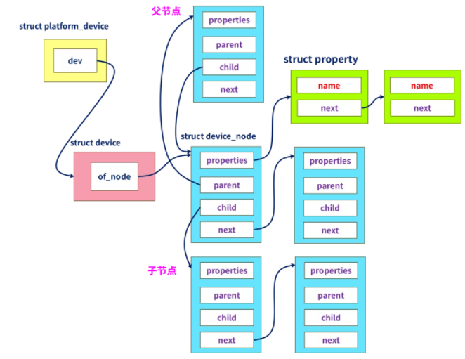
其中设备树信息会被转换成struct platform_device类型变量。
而驱动要解析设备树,必须定义 struct platform_driver类型结构体变量,并通过函数platform_driver_register()注册。
这两者都会注册到platform总线,当驱动和设备树节点匹配成功后,就调用 struct platform_driver中.probe方法。
其中设备树节点会封装在struct device_node结构体变量中 各个属性信息会封装在 struct property结构体变量中, 他们与struct platform_device结构体之间关系如下:
四、驱动架构
以下是一口君编写的驱动架构,
我们只需要将测试代码填充到hello_probe()中即可:
- static int hello_probe(struct platform_device *pdev)
- {
- printk("match ok \n");
- //解析代码编写
- return 0;
- }
- static int hello_remove(struct platform_device *pdev)
- {
- printk("hello_remove \n");
- return 0;
- }
- static struct of_device_id beep_table[] = {
- {.compatible = "yikoulinux"},
- };
- static struct platform_driver hello_driver =
- {
- .probe = hello_probe,
- .driver.name = "duang",
- .remove = hello_remove,
- .driver = {
- .name = "yikoupeng",
- .of_match_table = beep_table,
- },
- };
- static int hello_init(void)
- {
- printk("hello_init \n");
- return platform_driver_register(&hello_driver);
- }
- static void hello_exit(void)
- {
- printk("hello_exit \n");
- platform_driver_unregister(&hello_driver);
- return;
- }
- MODULE_LICENSE("GPL");
- module_init(hello_init);
- module_exit(hello_exit);
五、设备树节点
下面是给出的设备树信息:
- yikou_node{
- compatible = "yikoulinux";
- reg = <0x114000a0 0x4 0x139D0000 0x20>;
- reg-names = "peng";
- interrupt-parent=<&gpx1>;
- interrupts =<1 2>,<2 2>;
- csm_gpios=<&gpx2 3 0 &gpx2 4 0 &gpx2 5 0 &gpx2 6 0>;
- crl0_gpio=<&gpx0 5 0>;
- crl1_gpio=<&gpx0 6 0>;
- rst_gpio=<&gpx0 7 0>;
- cfg_gpio=<&gpx0 4 0>;
- phy_ref_freq = <26000>; /* kHz */
- suspend_poweroff;
- clock-names = "xusbxti",
- "otg";
- yikou_node {
- compatible = "leadcore,dsi-panel";
- panel_name = "lcd_rd_rm67295";
- refresh_en = <1>;
- bits-per-pixel = <32>;
- };
- };
其中包括常见reg、中断、整型值、bool值、字符串、子节点、时钟等属性。
一定要注意,很多属性的给出会因为使用的SOC平台的不同有所差异, 下面介绍下GPIO和中断编写原理:
1. GPIO
gpio信息的给出有以下两种方法:
- csm_gpios=<&gpx2 3 0 &gpx2 4 0 &gpx2 5 0 &gpx2 6 0>;
- crl0_gpio=<&gpx0 5 0>;
- crl1_gpio=<&gpx0 6 0>;
- rst_gpio=<&gpx0 7 0>;
- cfg_gpio=<&gpx0 4 0>;
第1种是公用同一个名字,第2种是每一个gpio单独使用1个名字。
gpio需要指明父节点,关于gpio父节点的说明下说明文档(通常linux-3.14\Documentation下有关于该内核版本的一些模块说明,很重要):
- linux-3.14\Documentation\devicetree\bindings\gpio.txt
- For example, the following could be used to describe gpios pins to use
- as chip select lines; with chip selects 0, 1 and 3 populated, and chip
- select 2 left empty:
- gpio1: gpio1 {
- gpio-controller
- #gpio-cells = <2>;
- };
- gpio2: gpio2 {
- gpio-controller
- #gpio-cells = <1>;
- };
- [...]
- chipsel-gpios = <&gpio1 12 0>,
- <&gpio1 13 0>,
- <0>, /* holes are permitted, means no GPIO 2 */
- <&gpio2 2>;
- Note that gpio-specifier length is controller dependent. In the
- above example, &gpio1 uses 2 cells to specify a gpio, while &gpio2
- only uses one.
- gpio-specifier may encode: bank, pin position inside the bank,
- whether pin is open-drain and whether pin is logically inverted.
- Exact meaning of each specifier cell is controller specific, and must
- be documented in the device tree binding for the device.
- Example of the node using GPIOs:
- node {
- gpios = <&qe_pio_e 18 0>;
- };
- In this example gpio-specifier is "18 0" and encodes GPIO pin number,
- and empty GPIO flags as accepted by the "qe_pio_e" gpio-controller.
翻译总结成如下几点:
gpio父节点需要包含属性
- gpio-controller、 表示是gpi控制器
- #gpio-cells = <2>; 表示子节点包括2个属性
对于子节点是2个属性的函数 比如:
- gpios = <&qe_pio_e 18 0>;
父节点是qe_pio_e 其中18表示GPIO pin值,就是gpio下面管理的pin脚序号,该pin值一般就需要查询用户手册&电路图。
2. 中断
中断属性节点如下:
- interrupt-parent=<&gpx1>;
- interrupts =<1 2>,<2 2>;
其中
- interrupt-parent=<&gpx1>;: 该中断信号所述的中断控制器
- interrupts =<1 2>,<2 2>; :描述中断属性,其中<>中第一个值表示该中断所述中断控制器index,第二个值表示中断触发方式
中断子节点格式如下:
- linux-3.14\Documentation\devicetree\bindings\gpio.txt
- Example of a peripheral using the GPIO module as an IRQ controller:
- funkyfpga@0 {
- compatible = "funky-fpga";
- ...
- interrupt-parent = <&gpio1>; #父节点
- interrupts = <4 3>; #节点属性
- };
中断子节点说明文档如下:
- linux-3.14\Documentation\devicetree\bindings\interrupt-controller\interrupts.txt
- b) two cells
- ------------
- The #interrupt-cells property is set to 2 and the first cell defines the
- index of the interrupt within the controller, while the second cell is used
- to specify any of the following flags:
- - bits[3:0] trigger type and level flags
- 1 = low-to-high edge triggered 上升沿
- 2 = high-to-low edge triggered 下降沿
- 4 = active high level-sensitive 高电平有效
- 8 = active low level-sensitive 低电平有效
我们所填写的中断父节点gpx1定义如下(该文件由三星厂家出厂定制好):
- linux-3.14\arch\arm\boot\dts\exynos4x12-pinctrl.dtsi
- gpx1: gpx1 {
- gpio-controller; #gpio控制器
- #gpio-cells = <2>; #子节点有2个属性
- interrupt-controller; #中断控制器
- interrupt-parent = <&gic>; #父节点gic
- interrupts = <0 24 0>, <0 25 0>, <0 26 0>, <0 27 0>, #子节点属性约束
- <0 28 0>, <0 29 0>, <0 30 0>, <0 31 0>;
- #interrupt-cells = <2>;
- };
可见三星的exynos4412平台中gpx1,既可以做gpio控制器又可以做中断控制器,而gpx1作为中断控制器则路由到gic上。其中interrupts属性说明如下:
- linux-3.14\Documentation\devicetree\bindings\arm\gic.txt
- Main node required properties:
- - compatible : should be one of:
- "arm,gic-400"
- "arm,cortex-a15-gic"
- "arm,cortex-a9-gic"
- "arm,cortex-a7-gic"
- "arm,arm11mp-gic"
- - interrupt-controller : Identifies the node as an interrupt controller
- - #interrupt-cells : Specifies the number of cells needed to encode an
- interrupt source. The type shall be a <u32> and the value shall be 3.
- The 1st cell is the interrupt type; 0 for SPI interrupts, 1 for PPI
- interrupts.
- The 2nd cell contains the interrupt number for the interrupt type.
- SPI interrupts are in the range [0-987]. PPI interrupts are in the
- range [0-15].
- The 3rd cell is the flags, encoded as follows:
- bits[3:0] trigger type and level flags.
- 1 = low-to-high edge triggered
- 2 = high-to-low edge triggered
- 4 = active high level-sensitive
- 8 = active low level-sensitive
- bits[15:8] PPI interrupt cpu mask. Each bit corresponds to each of
- the 8 possible cpus attached to the GIC. A bit set to '1' indicated
- the interrupt is wired to that CPU. Only valid for PPI interrupts.
翻译总结:
- interrupts = <0 24 0>
第1个0 表示该中断是SPI类型中断,如果是1表示PPI类型中断
24表示中断号(通过查询电路图和datasheet获得)
第三个0表示中断触发方式
再强调一遍 不同的平台gpio、中断控制器管理可能不一样,所以填写方法可能会有差异,不可教条
六、驱动提取设备树信息方法
驱动解析代码与设备树节点之间关系如下,代码与属性用相同颜色框出:
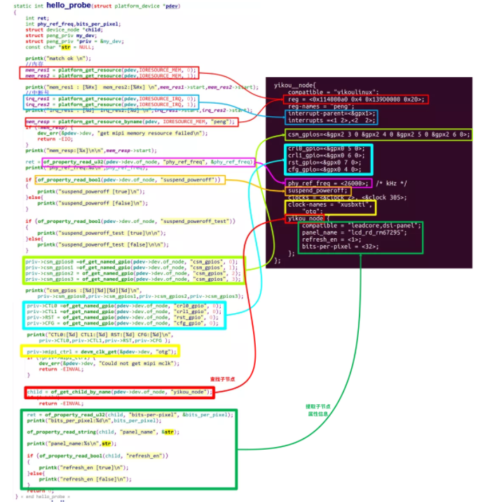
of开头的函数请参考《手把手教linux驱动11-linux设备驱动统一模型》
七、编译(ubuntu中操作)
驱动编译:
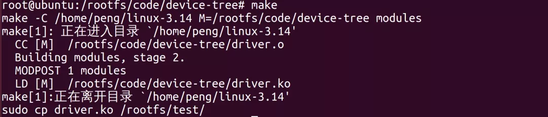
注意,内核必须提前编译好
设备树编译:

编译设备树命令,各个厂家的SDK都不尽相同,本例制作参考。
除此之外驱动模块文件、设备树文件如何导入给开发板,差别也比较大,本文不再给出步骤。
八、加载模块(开发板上操作)
加载模块后执行结果如下:
- [root@peng test]# insmod driver.ko
- [ 26.880000] hello_init
- [ 26.880000] match ok
- [ 26.880000] mem_res1 : [0x114000a0] mem_res2:[0x139d0000]
- [ 26.885000] irq_res1 : [168] irq_res2:[169]
- [ 26.890000] mem_resp:[114000a0]
- [ 26.890000]
- [ 26.895000] phy_ref_freq:26000
- [ 26.900000] suspend_poweroff [true]
- [ 26.900000] suspend_poweroff_test [false]
- [ 26.900000]
- [ 26.905000] csm_gpios :[231][232][233][234]
- [ 26.910000] CTL0:[217] CTL1:[218] RST:[219] CFG:[216]
- [ 26.915000] bits_per_pixel:32
- [ 26.920000] panel_name:lcd_rd_rm67295
- [ 26.925000] refresh_en [true]
其中打印的信息就是最终我们解析出的设备树里的硬件信息, 我们就可以根据这些信息进行相关资源申请、初始化。
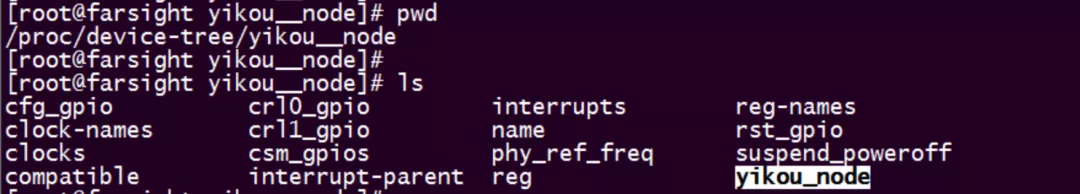
同时设备树中的信息,会以文件节点形式创建在一下目录中:
本文转载自微信公众号「一口Linux」

评论暂时关闭